-
Jiangsu Acrel Electrical Manufacturing Co., LTD.
-
tel:
+86 18761509710 -
email:
besty.chen@email.acrel.cn


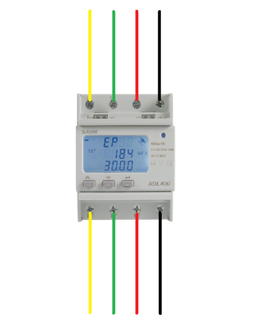
Three Phase Din Rail Energy Meter ADL400
● Rated Current: 1 (6) A, 10 (80) A
● Rated Voltage: AC220V/380V, AC230V/400V
● RS485(MODBUS-RTU) Communication
● 12 digits LCD Display; 35mm DIN Rail Installation
● Multi-tariff: 4 Tariff Rates (Spike, Peak, Valley and Flat kWh)
● 2~31st Harmonic Measurement
● MID Certified
● Set parameters
● kWh Class 0.5S



General
ADL400 three phase din rail electric meter is a smart meter designed for power supply system, industrial and mining enterprises and utilities to calculate the electricity consumption and manage the electric demand. It features LCD display, high precision, small size and simple installation.
It integrates the measurement of all electrical parameters with the comprehensive electricity metering and management provides various data on previous 48 months, checks the 31st harmonic content and the total harmonic content, realizes the remote communication and the remote control with switching input and relay output and boasts the alarm output.
It is fitted with RS485 communication port and adapted to MODBUS-RTU protocol. ADL400 can be used in all kinds of control systems, SCADA system and energy management system (EMS). The meter meets the related technical requirements of electronic meter in the IEC62053-21standards.
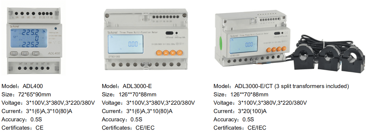
Specification
|
Specification |
ADL400 |
ADL3000-E |
ADL3000-E/CT |
||
|
Voltage |
Reference voltage |
3×100V、 3×380V、3×57.7/100V、 3×220/380V |
|||
|
Consumption |
<10VA |
||||
|
Impedance |
>2MΩ |
|
|
||
|
Accuracy |
Error±0.2% |
|
|
||
|
Current |
Reference current |
3×1(6)A,3×10(80)A |
3×1(6)A,3×10(80)A |
3×1(6)A,3×20(100)A |
|
|
Accuracy class |
Error±0.2% |
||||
|
Consumption |
<1VA |
||||
|
Power |
Active, reactive, apparent power, error±0.5℅ |
||||
|
Display |
LCD |
||||
|
Frequency |
45~65Hz,Error±0.2% |
||||
|
Option Function |
Communication |
RS485, Modbus-RTU compatible protocol |
|||
|
Multi tariff energies |
Adapt 4 time zones, 2 time interval lists, 14 time interval by day and 4 tariff rates |
||||
|
Harmonic |
No |
2-31st harmonic. |
|||
|
Switching |
No |
1 Switching output |
|||
|
NO |
1 optocoupler input |
||||
|
Operation Temperature |
-25 ºC~+55 ºC |
||||
|
Storage Temperature |
-25 ºC ~+70 ºC |
||||
|
Altitude |
≤ 2500m |
||||
|
Relative humidity |
≤95%RH, no condensation, without corrosive gas |
||||
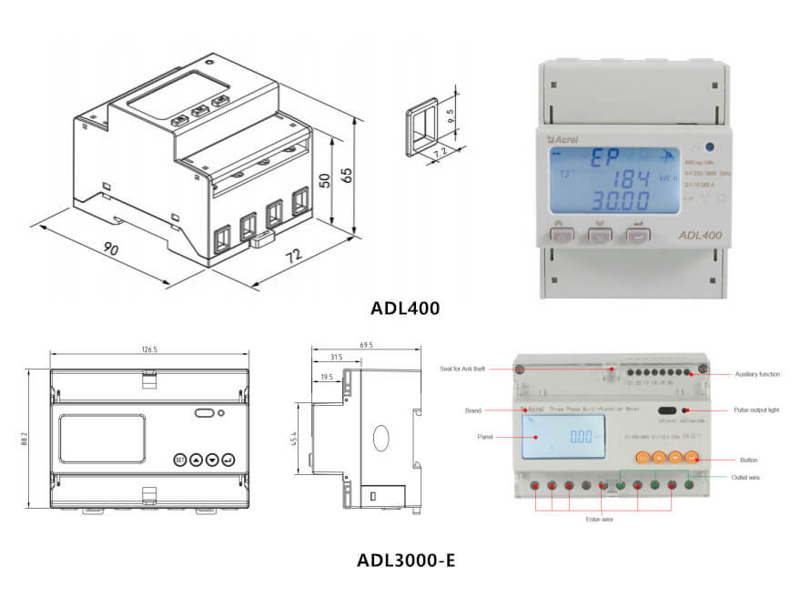
Dimension
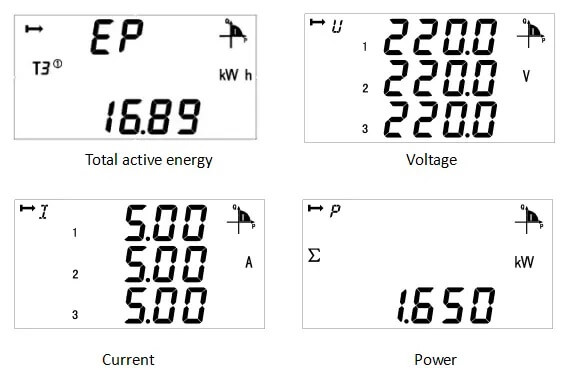
LCD Display
Wiring
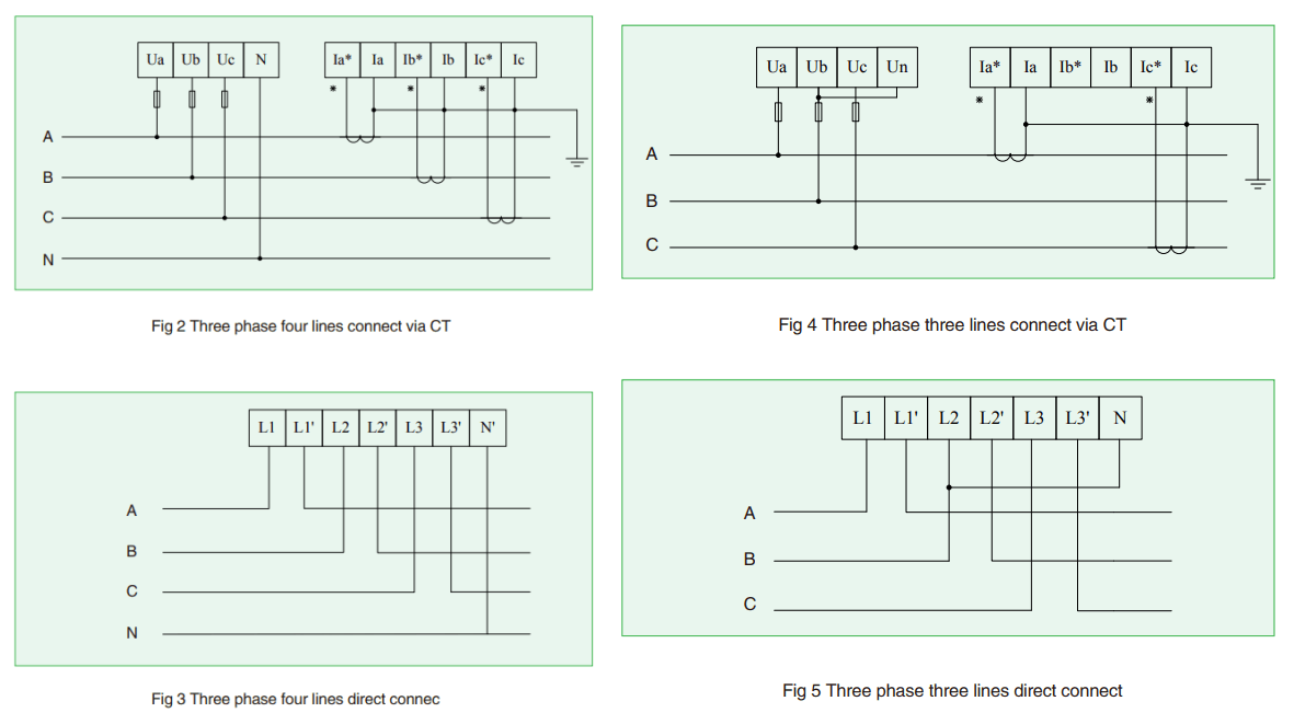
Wiring sample of current and voltage
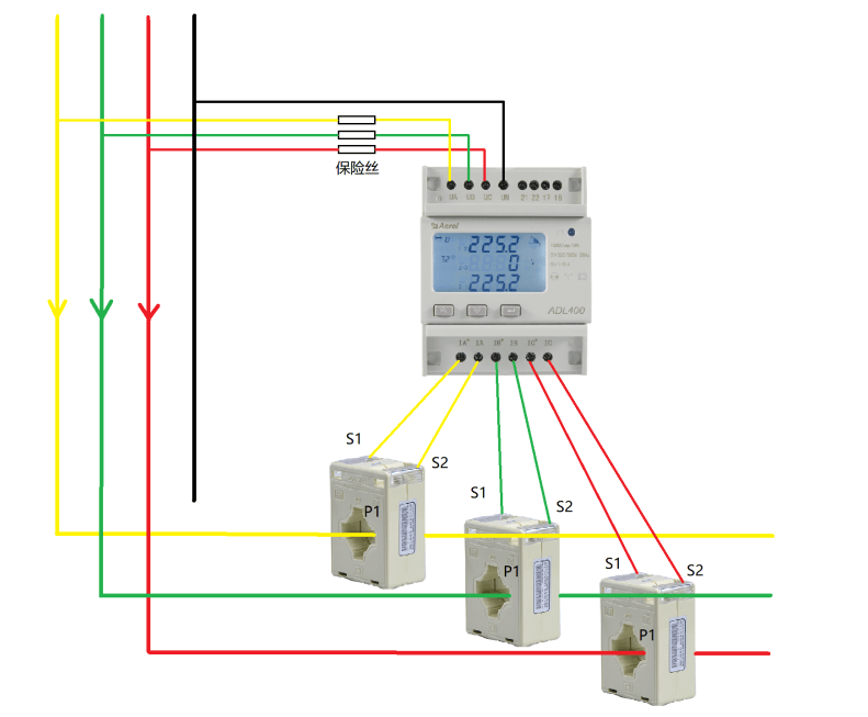
3 phase 4 wire Secondary CT Access & 3 phase 4 wire Direct Access
Installation
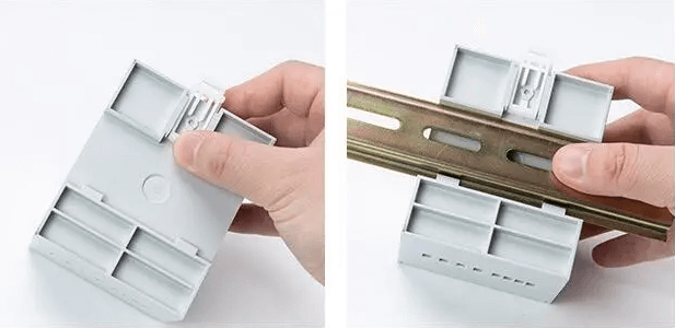
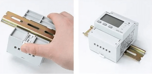
Din Rail 35mm
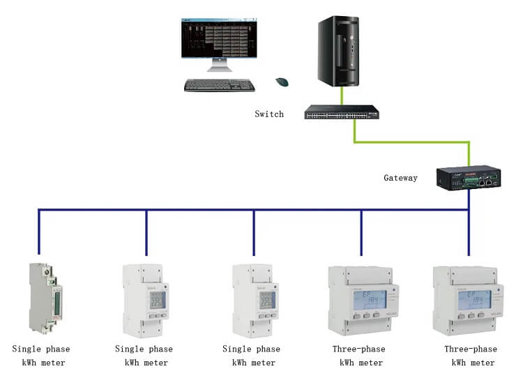
Typical Connection
Related Solution
|
voltage |
Nominal voltage |
AC 220V |
||
|
Nominal frequency |
50Hz |
|||
|
consumption |
<10VA |
|||
|
current |
Maximum current |
80A |
||
|
Starting current |
0.01A |
|||
|
Consumption |
<1VA |
|||
|
Measurement performance |
Accuracy |
kWh Class 0.5 |
||
|
Range |
0~9999999999.99kWh |
|||
|
Clock |
accuracy |
Error ≤0.5s/d |
||
|
Active pulse |
width |
80±20ms |
||
|
constant |
1000imp/kWh,10000imp/kWh |
|||
|
Communication |
Interface |
RS485 |
||
|
Protocol |
MODBUS-RTU |
|||
|
Temperature range |
Work |
-25℃~55℃ |
||
|
Storage |
-40℃~70℃ |
|||
|
humidity |
≤95%(No condensation) |
|||
|
Altitude |
<2000m |
|||
Q: The display power or energy count is inaccurate after the meter powered on.
A: Switch the meter display interface to the power (active power P, power factor λ) interface, and check whether the power display is negative or not. And whether the power factor is between 0.9-0.95, and then check whether the incoming and outgoing wires of the current signal wire are connected reversely (that is, the current the incoming wire must be the same as the incoming wire end of the meter), and consistent with the wiring diagram on the meter.
Q: It cannot communicate with the host computer normally after the instrument powered on.
A: 1. The voltage value between the communication output A and B of the measuring instrument should be between +(4.4-4.5)V .
2. Check whether the communication wiring method is correctly wired according to the wiring diagram (that is the communication terminal A/B of the instrument must be connected with corresponding to communication serial port A/B);
Related Products


CONTACT US
Contact US
Product Information
Quantity
Unit
Piece
Support order samples, customization, wholesale direct, and complete payment. If the product you look for does not have corresponding customized content, pls fill out the form below to contact us, and we will reply ASAP.