
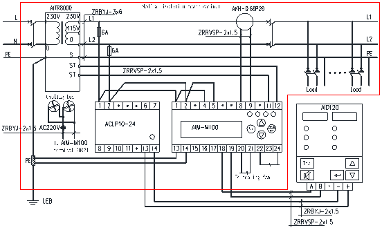
Typical Connection
-
Jiangsu Acrel Electrical Manufacturing Co., LTD.
-
tel:
+86 18761509710 -
email:
besty.chen@email.acrel.cn


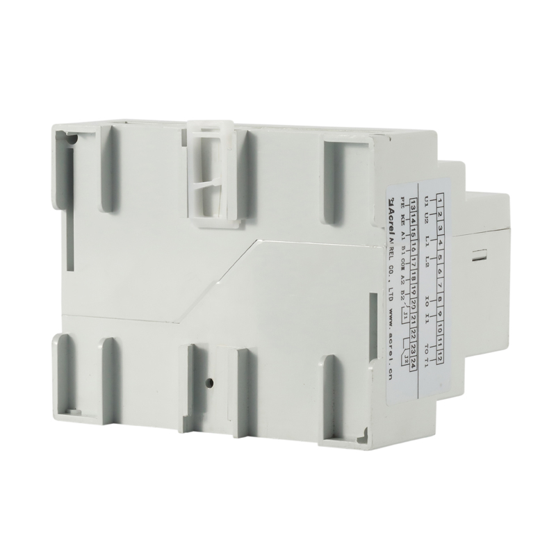
AIM-M100 Medical Insulation Monitor
● Insulation monitoring for medical IT systems
● Load and temperature monitoring of isolation transformer
● Device disconnection monitoring
● LED indicators: On, Insulation, Overload, Overtemp
● Alarm relay output
● Test button
● Insulation fault location
● RS485 (MODBUS-RTU) + CAN

description1
Zipper closure
1/5 zip athletic pullovers for men. Stretchy, lightweight, fast-drying
fabric for superior performance.
REGULAR FIT - US standard sizes. An athletic fit that sits close to the
body
for a wide range of motion, designed for optimal performance and all day
comfort.
FEATURES - Quarter zip closure;Thumbholes on long sleeves to keep them
in
place during workout
product detail
General
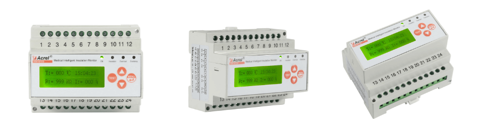
AIM-M100 auxiliary power supply is AC220V, the product does not have insulation fault location. AIM-M200 auxiliary power is DC 24V. It has all the monitoring functions of AIM-M10 and AIM-M100 products, it also supports the insulation fault location. If you need insulation fault location, please choose AIM-M200. The positioning function can also be turned off through the menu.
Function
1) Functions of real-time monitoring and fault alarming of the ground insulation resistance, transformer load current and transformer winding temperature of the monitored IT system;
2) Can be used with insulation fault locator, remotely starting fault-locating and displaying locating results when there are insulation faults;
3) Real-time monitor the line disconnection fault, temperature sensor disconnection fault and the functional grounding line disconnection fault of the monitored system, and give the alarm indication when the fault occurs;
4) Relay alarm output, LED alarm indication and other faults indication functions;
5) Two kinds of fieldbus communication technology, which are used for centralized alarm and display instrument, test signal generator, insulation fault locator and upper computer management software communications, and can monitor the operation status of IT system in real time.
6) Events logging function, which can record alarm occurrence time and fault type and is convenient for operation personnel to analyze the operation conditions of system and promptly eliminate the faults;
Specification

Product Selection

Dimension
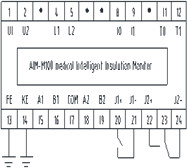
Wiring & Installation
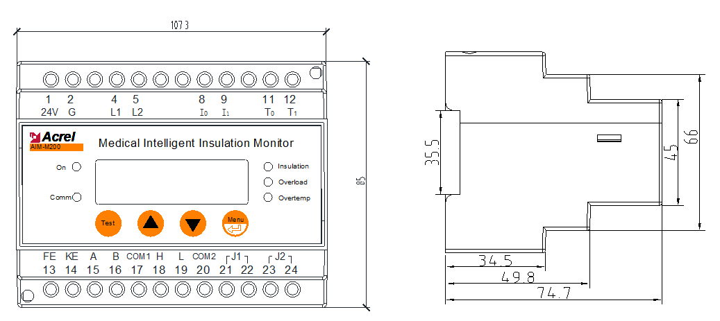
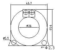
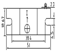
Installation size of AKH-0.66P26 is shown in the following figure:
-
Front View
-
Bottom View
LED Indicator Instruction
|
Indicator light |
Instruction |
|
On |
When the device is in normal operation, the indicator flashes, and the flickering frequency is about once a second. |
|
Insulation |
When the insulation resistance exceeds the alarm setting value, or when FK/LL is disconnected, the indicator flashes to alarm. |
|
Overload |
When the system load current exceeds the alarm setting value, the indicator flashes to alarm. |
|
Overtemp |
When the transformer temperature exceeds the alarm setting value or the temperature sensor wiring is disconnected, the indicator flashes to alarm. |
Data Settings
|
First Menu |
Second Menu |
Range and Description |
|
SET Comm |
Set Addr1 |
1-247 |
|
Set Baud1 |
4800,9600,19200 |
|
|
Set Addr2 |
1-247 |
|
|
Set Baud2 |
4800,9600,19200 |
|
|
Set Alarm |
Temp |
0-200 |
|
Resistance |
50-999 |
|
|
Current |
14,18,22,28,35,45 |
|
|
Relay Mode |
DO-1 |
Normal Off, Normal On |
|
DO -2 |
22-24 23; |
|
|
Set Time |
Date |
Year-month-day |
|
Time |
Hour: minute: second |
|
|
Set Password |
0000-9999kWh |
|
|
Interface Mode |
0-2 |
|
|
Factory Reset |
Restore factory settings |
|
|
Software Version |
Firmware version information |
|
Common Problems
Make sure the connection is correct before the system is powered on. For common problems, according to the fault phenomena in the table below, targeted investigation can be carried out.
|
Fault Phenomenon |
Possible Causes and Troubleshooting |
|
LCD: LL break, Insulation indicator lighting. |
Terminal 4 and terminal 5 of AIM-M100 are not reliably connected to L1 and L2 of the IT system. Check the connection and make sure it is reliable. |
|
LCD: FK break, Insulation indicator lighting. |
Terminal 13 and terminal 14 of AIM-M100 are not reliably connected to LEB. Check the connection and make sure it is reliable. |
|
LCD: TC break, Overtemp indicator lighting. |
Terminal 11 and terminal 12 of AIM-M100 are not reliably connected to the two ST terminals of the isolation transformer. Check the connection and make sure it is correct. |
|
LCD: insulation fault, Insulation indicator lighting. |
At least one of the L1 and L2 wires in IT system has grounding fault, which can be restored to normal after removal. |
|
The device can't light up. |
The working power supply of AIM-M100 is not connected properly. Check the connection of terminals 1 and 2 and make sure it is correct. |
Note: All the above faults should be checked by power off, and the wiring should be adjusted until everything is normal.
parameter
|
AUX Power |
Voltage |
AC220V±10% |
Temperature monitoring |
Thermal resistor |
2 Pt100 |
|
Power consumption |
≤8VA |
Measuring range |
-50~+200℃ |
||
|
Insulation Monitoring |
Resistance measuring range |
10~999kΩ |
Alarm value range |
0~+200℃ |
|
|
Response value |
50~999kΩ |
Alarm Output |
Output mode |
2 Relays |
|
|
Relative uncertainty |
±10% |
Contact rating |
AC 250V/3A DC 30V/3A |
||
|
Response time |
≤3s |
Environment |
Operating temperature |
-10~+55℃ |
|
|
Permissible system leakage capacitance Ce |
≤5uF |
Transport temperature |
-25~+70℃ |
||
|
Measuring voltage Um |
≤12V |
Storage temperature |
-25~+70℃ |
||
|
Measuring current Im |
≤50uA |
Relative humidity |
5%-95%,No condensation |
||
|
Impedance Zi |
≥200kΩ |
Altitude |
≤2500m |
||
|
Internal DC resistance Ri |
≥240kΩ |
IP degree |
IP30 |
||
|
Permissible extraneous DC voltage Ufg |
≤DC280V |
Rated impulse voltage / pollution degree |
4KV/Ⅲ |
||
|
Load Current Monitoring |
Measuring Value |
2.1~50A |
EMC |
IEC 61326-2-4 |
|
|
Alarm Value |
5~50A |
Communication |
RS485(Modbus-RTU) |
||
|
Measuring accuracy |
±5% |
||||
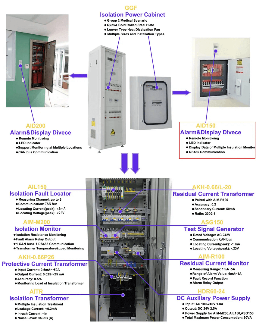
ISOLATION POWER CABINET
Related Products


CONTACT US
Contact US
Product Information
Quantity
Unit
Piece
Support order samples, customization, wholesale direct, and complete payment. If the product you look for does not have corresponding customized content, pls fill out the form below to contact us, and we will reply ASAP.