-
Jiangsu Acrel Electrical Manufacturing Co., LTD.
-
tel:
+86 18761509710 -
email:
besty.chen@email.acrel.cn


ASG150 Test Signal Generator
● Generating Fault Location Signal


General
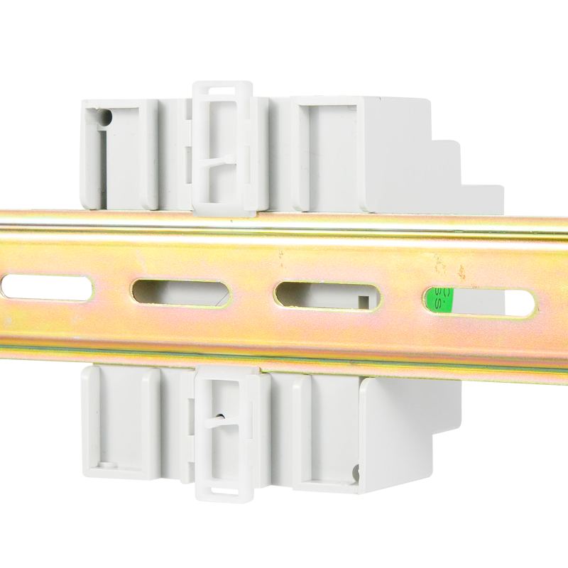
ASG series test signal generator adopts 32-bit microprocessor chip and high-precision signal generation circuit to realize the generation of specific test signal. When the monitored IT system has insulation faults, it can start up and produce test signal in time, working with the insulation. Fault locator to realize insulation fault location.
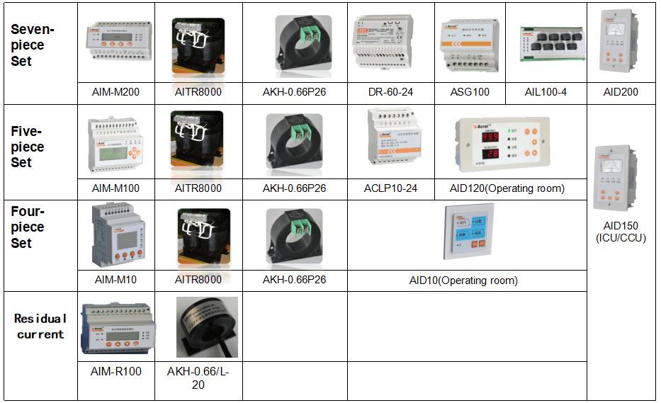
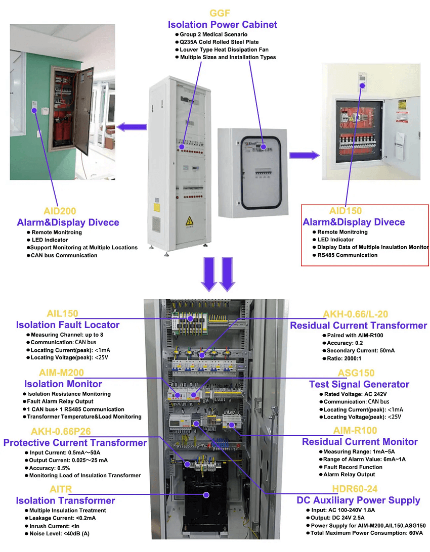
The test signal generator ASG in conjunction with AIM-M200 medical intelligent insulation monitor and AIL100 insulation fault locator are designed for insulation fault location in medical IT system.
Dimension

Product Selection
Typical Connection

LED Indicator Instructions
| Indicator light | Instructions |
| On | When the device is in normal operation, the indicator flashes, and the flickering frequency is about once a second. |
|
Comm |
Indicate the status of device communication, when there is data transmission, the indicator flashes. |
| Test |
When the indicator light is green, it indicates normal operation of the system;
When red, it indicates the instrument has L1, L2 disconnection fault; When the red and green flash alternately, it indicates the device is generating fault location signals. |
Common Problems
Make sure the connection is correct before the system is powered on. For common problems, according to the fault phenomena in the table below, targeted investigation can be carried out.
|
No. |
Fault phenomenon |
Possible causes and troubleshooting |
|
1 |
The device is not lit. |
The 24V power supply is not connected properly. Check the connection of terminals 8 and 9 and make sure it is correct. |
|
2 |
Test indicator is red. |
Terminals 3 and 5 are not reliably connected to the secondary side of the isolation transformer. Check and make sure that the connection is correct until the light turns green after power on. |
Note: All the above faults should be checked by power off, and the wiring should be adjusted until everything is normal.
|
Auxiliary power supply |
Voltage |
DC24V(±25%) |
|
Power consumption |
≤2VA |
|
|
Monitored system |
Rated voltage |
0~242V AC |
|
Rated frequency |
45-60Hz |
|
|
Locating current |
<1mA |
|
|
Communication |
Interface |
CAN bus |
Related Products


CONTACT US
Contact US
Product Information
Quantity
Unit
Piece
Support order samples, customization, wholesale direct, and complete payment. If the product you look for does not have corresponding customized content, pls fill out the form below to contact us, and we will reply ASAP.